Welding with a MIG (Metal Inert Gas) machine can look easy, but the right settings make all the difference. Many beginners struggle with poor welds simply because their machine isn’t dialed in for the job. A MIG welding settings chart is like a shortcut—it quickly tells you the best voltage, wire speed, and gas flow for your material and wire size. When you understand how to use this chart, your welds get stronger, cleaner, and more professional.
Let’s break down what these charts show, why they matter, and how you can use them to improve your results—whether you’re a hobbyist, student, or new to fabrication.
What Is A Mig Welding Settings Chart?
A MIG welding settings chart is a reference guide. It lists recommended machine settings for different materials, thicknesses, and wire types. Charts help you:
- Set the right voltage (power level)
- Adjust wire feed speed (how fast the wire comes out)
- Choose the correct gas flow (for shielding)
- Match wire size to the job
Most charts are printed on the inside of your welder’s door or included in the manual. They’re built from expert testing, so they save you time and guesswork.
Key Mig Welding Settings Explained
Before using a chart, it helps to know what each setting does:
- Voltage: Controls the arc’s heat and width. Too low, and you get weak welds; too high, and you burn through.
- Wire Feed Speed (WFS): Regulates how much filler wire enters the weld pool. Too fast, and the wire piles up; too slow, and the arc is unstable.
- Gas Flow Rate: Delivers shielding gas to protect your weld from air. Too much wastes gas, too little lets in contamination.
- Wire Diameter: Common sizes are 0.023″, 0.030″, and 0.035″. Thicker wires carry more power for heavy jobs.
Understanding these basics helps you read and use a settings chart effectively.

Credit: weldmongerstore.com
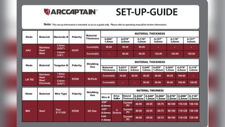
Sample Mig Welding Settings Chart For Mild Steel
Here’s a practical chart for mild steel using C25 (75% Argon/25% CO2) gas and solid wire. These are starting points—fine-tune as needed.
| Material Thickness (inches) | Wire Diameter (inches) | Voltage (V) | Wire Feed Speed (ipm) | Gas Flow (cfh) |
|---|---|---|---|---|
| 1/16″ | 0.023 | 16-17 | 180-200 | 20-25 |
| 1/8″ | 0.030 | 17-19 | 260-280 | 25-30 |
| 1/4″ | 0.035 | 20-22 | 300-340 | 30-35 |
Tip: Always start with the chart, then adjust while test-welding on scrap metal.
How To Use A Mig Welding Settings Chart
- Identify your material (type and thickness).
- Find the wire size you’re using.
- Set voltage and wire speed as the chart recommends.
- Adjust gas flow to match.
- Test on scrap—watch the weld and listen for a steady “frying bacon” sound.
If the weld is too tall or the bead is inconsistent, tweak your settings slightly. Charts are not absolute rules—they’re smart starting points.
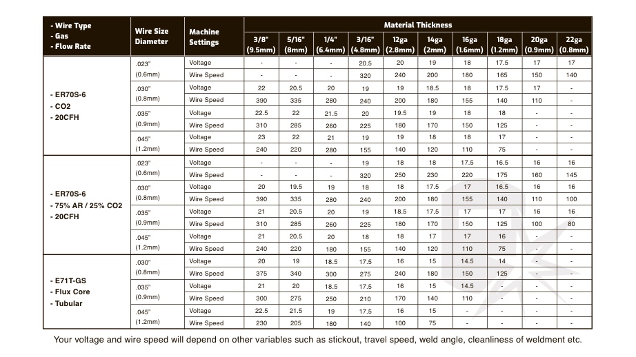
Table: Voltage And Wire Feed For Common Materials
Different metals need different settings. Here’s a quick comparison for mild steel, stainless, and aluminum.
| Metal Type | Wire Diameter (inches) | Voltage (V) | Wire Feed Speed (ipm) | Shielding Gas |
|---|---|---|---|---|
| Mild Steel | 0.030 | 18 | 265 | 75/25 Argon/CO2 |
| Stainless Steel | 0.030 | 20 | 300 | 98/2 Argon/O2 |
| Aluminum | 0.030 | 21 | 330 | 100% Argon |
Factors That Affect Your Settings
Charts are helpful, but real-world conditions also matter. Here are two things beginners often miss:
- Extension Cord Length: Long cords lower voltage, so your settings may need a bump up for the same results.
- Welding Position: Overhead or vertical welds require slightly less voltage and wire speed compared to flat welds.
Also, environmental factors like wind can blow shielding gas away, causing porosity. Always shield your work area if welding outdoors.
Common Problems When Settings Are Wrong
- Burn-through: Voltage too high, or wire speed too slow
- Cold lap/lack of fusion: Voltage too low, or wire speed too high
- Excess spatter: Wrong gas, incorrect settings, or dirty metal
A good chart helps avoid these, but always check your weld visually.
Table: Troubleshooting Mig Weld Quality
Let’s link common weld issues with likely causes and fixes.
| Problem | Possible Cause | Suggested Fix |
|---|---|---|
| Porosity (holes) | Low gas flow, drafts | Increase flow, block wind |
| Weld sits too high | Wire speed too fast | Lower wire speed |
| Burn-through | Voltage too high | Reduce voltage or move faster |

Credit: www.mig-welding.co.uk
Should You Trust All Mig Welding Charts?
Most charts from reputable manufacturers are reliable. However, cheap or generic welders sometimes print incorrect charts. If your results look wrong, consult resources like the Lincoln Electric Welding Education Center for trusted data.
Quick Tips For Better Mig Welds
- Clean your metal—rust or paint ruins weld quality.
- Use the correct polarity (DCEP for solid wire).
- Keep your gun angle at 10-15° for flat welds.
- Change contact tips if wire feeding is inconsistent.
Credit: weldguru.com
Frequently Asked Questions
What Happens If My Wire Speed Is Too High?
If your wire feed speed is too high, the wire can pile up and create a tall bead. You may hear sputtering or even see the wire “stubbing” against the metal. Reduce the speed until you hear a smooth, steady arc.
Do I Need To Change Settings For Different Positions?
Yes. Vertical or overhead welds often use slightly lower voltage and wire speed to control the weld pool. Practice and small adjustments are important—charts are a starting point.
Why Does My Weld Have Holes (porosity)?
Porosity usually means not enough shielding gas or wind blowing away the gas. Check for leaks, increase the gas flow, and block any drafts in your workspace.
Can I Use The Same Settings For Flux-cored Wire?
No. Flux-cored wire often needs higher voltage and works without shielding gas. Check your welder’s manual for flux-core settings, as they are different from solid wire settings.
Where Can I Find More Mig Welding Charts?
Most major brands print charts inside their welders or on their websites. For extra detail, visit the Lincoln Electric Welding Education Center or other trusted industry sites.
A MIG welding settings chart is your shortcut to better welds. Learn to read it, test your settings, and adjust for your real-world conditions. With practice, you’ll get cleaner, stronger welds every time you strike an arc.